
Here is the professional English translation of your technical document, tailored for engineering and environmental compliance contexts:
Project Overview
For the construction of two 55-hole, 6.25-meter single-heating stamp-charged coke ovens, one denitrification unit is installed. This unit treats flue gas from the coke oven stacks, high-sulfur gas from dry quenching (reserved), and acid production tail gas.
Original Flue Gas Parameters:
|
Section |
Gas Volume (Nm³/h) |
NOx (mg/m³) |
SO₂ (mg/m³) |
Particulates (mg/m³) |
Temp (℃) |
|
Coke Oven Flue Gas |
320,000 |
500 |
200 |
50 |
260 |
|
1# Dry Quenching High-Sulfur Gas (Reserved) |
30,000 |
- |
1800 |
30 |
160 |
|
2# Dry Quenching High-Sulfur Gas (Reserved) |
30,000 |
- |
1800 |
30 |
160 |
|
Acid Production Tail Gas (Reserved) |
5,000 |
240 |
200 |
- |
25 |
The flue gas emission indexes after treatment of the denitrification unit for this project are listed in the table below.
| Item | Particulate Matter (mg/Nm³) | SO₂ (mg/Nm³) | NOₓ (mg/Nm³) | Reference Oxygen Content (%) |
|---|---|---|---|---|
| Desulfurization & Denitrification | ≤10 | ≤15 | ≤100 | 8 |
Process Technology Overview
his project adopts the process of calcium-based dry desulfurization + particulate matter recovery + low-temperature SCR denitrification + waste heat recovery to purify coke oven flue gas through desulfurization, denitrification and dust removal, as well as waste heat recovery, so as to achieve pollutant discharge up to standard.
The desulfurization and denitrification unit extracts coke oven flue gas from the underground flue duct connection, which mixes with high-sulfur flue gas from coke dry quenching (CDQ) and is then delivered to the desulfurization tower. The dry desulfurization unit injects the desulfurizer Ca(OH)₂ into the flue gas pipeline. The calcium-based powder fully contacts and chemically reacts with SO₂ in the flue gas inside the desulfurization tower to absorb and purify SO₂.
The flue gas after desulfurization enters the integrated dust removal and denitrification unit. It first passes through baghouse dust removal; dry particulate matter in the flue gas is filtered and collected by filter bags. The dust layer on the filter bags further removes SO₂ from the flue gas and adsorbs viscous components such as tar.
The dedusted flue gas is thoroughly mixed with the reducing agent (ammonia) dosed by the ammonia injection device. The mixed flue gas flows into the denitrification catalyst layer, where reduction reactions take place under the action of the catalyst to remove NOₓ. The purified clean flue gas recovers waste heat via a waste heat boiler and is then sent back to the chimney for emission by the system induced draft fan. The exhaust temperature of the purified flue gas is above 140°C, which meets the temperature requirement for chimney hot standby.
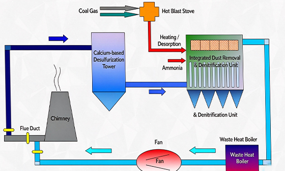
ocess Flow Diagram of Coke Oven Denitrification Unit Denitrification Principle (NH₃-SCR Method)
More than 90% of NOₓ in flue gas exists in the form of NO. The denitrification system uses ammonia (NH₃) as the reducing agent. Under the action of the SCR catalyst, ammonia reacts with NOₓ in flue gas to generate N₂ and H₂O for NOₓ removal, while controlling the ammonia slip rate.
Chemical reaction equations: 4NO + 4NH₃ + O₂ → 4N₂ + 6H₂O 2NO₂ + 4NH₃ + O₂ → 3N₂ + 6H₂O
Ammonia is adopted as the reducing agent in this project. Ammonia is generated by the supporting ammonia water evaporation unit and transported to the denitrification unit through pipelines.
Process System Composition
The coke oven flue gas denitrification unit is mainly composed of flue gas system, desulfurization system, ammonia injection system, etc.
Flue Gas System
It mainly consists of coke oven flue gas pipelines, valves, expansion joints, denitrification induced draft fan, pipeline accessories and thermal insulation.
A pneumatic control valve is designed on the gas extraction pipeline, and an electric return air valve is arranged after the fan. When the flue gas purification system is in operation, the flue gas shut-off valve is closed, and the pneumatic control valve on the gas extraction pipeline and the electric return air valve of the fan are opened to guide flue gas into the purification system. The purified clean flue gas is sent back to the coke oven flue by the induced draft fan. When the purification system is shut down, the electric flue gas shut-off valve is opened, and the pneumatic gas extraction valve and the electric return air valve behind the fan are closed. Flue gas is directly discharged to the chimney without affecting the normal production of the coke oven.
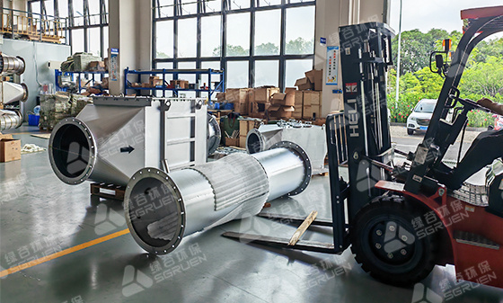
The pressure loss of the flue gas purification system is mainly overcome by the induced draft fan. A centrifugal fan is adopted as the induced draft fan. The fan adjusts pressure and flow via a frequency converter and is interlocked with the coke oven heating system. It can not only meet the requirement of suction adjustment for coke oven heating, but also achieve energy saving.
The desulfurization and denitrification induced draft fan is arranged outdoors. The bearing is cooled by water cooling. The cooling water pipeline is equipped with electric heat tracing and thermal insulation on the exterior. When the ambient temperature drops, the electric heat tracing for cooling water is activated to ensure stable operation of the fan.
The main flue gas pipelines for desulfurization and denitrification adopt materials and wall thickness in accordance with design specifications. Stiffeners are arranged transversely, and thermal insulation cladding is installed on the outer side of flue gas pipelines.
| Item | Flue Gas Flow Rate under Working Condition (m³/h) | Flue Gas Temperature (℃) | Fan Total Pressure (Pa) | Motor Power (kW, 10kV) |
|---|---|---|---|---|
| Induced Draft Fan | 650000 | 165 | 5800 | 1800 |
Dust Removal and Denitrification System
The dust removal and denitrification system consists of an integrated dust removal & denitrification unit, ammonia distribution device and hot air device.
The flue gas after dry desulfurization enters the integrated dust removal & denitrification unit for dust removal and denitrification treatment.
The dust removal section features high-efficiency dust removal and is equipped with high-temperature resistant filter bags (280℃). The filter bag adopts PTFE membrane-laminated composite filter material, with a dust removal efficiency up to 99.9% and dust emission concentration lower than 10 mg/Nm³. It can realize the recovery of desulfurization ash from the dry desulfurization process and the purification of particulate matter in coke oven flue gas. Meanwhile, the desulfurizing agent accumulated on the bag surface continues to chemically react with residual SO₂ in flue gas to further improve the desulfurization efficiency of the dry process.
The dust removal section is fitted with an ash cleaning device using compressed air as the purge medium. The ash cleaning frequency can be set according to actual operating conditions, or controlled based on the pressure differential across the filter bags inside the reactor. The integrated dust removal & denitrification unit is arranged vertically: the lower part is the dust removal section and the upper part is the denitrification section. The dust removal section is provided with ports for on-line differential pressure monitoring and manual differential pressure measurement.
The housing of the integrated dust removal & denitrification unit adopts a compartmentalized design to allow off-line bag replacement and off-line ash cleaning.
The dedusted flue gas is fully mixed with the reducing agent (ammonia) dosed by the ammonia distributor. The mixed flue gas flows upward into the SCR catalyst layer for denitrification. Denitrification reaction occurs under the action of catalyst to remove NOₓ. When the flue gas temperature ≥ 180℃, the denitrification efficiency is no less than 90%, and the NOₓ emission concentration is lower than 100 mg/Nm³.
Valves are installed at the flue gas inlet and outlet of each module of the integrated dust removal & denitrification unit. Replacement and maintenance of filter bags and catalysts can be carried out module by module. In-situ thermal regeneration of catalysts can also be implemented module by module. This extends the high-efficiency service life of low-temperature denitrification catalysts, and enables off-line maintenance without interrupting the operation of the entire purification system.
Main technical parameters of the integrated dust removal & denitrification unit:
| Equipment Name | Flue Gas Flow (Nm³/h) | Inlet Temperature (℃) | Filtration Area (m²) | Dust Removal Compartments (pcs) | Catalyst Volume (m³) | Catalyst Compartments (pcs) |
|---|---|---|---|---|---|---|
| Integrated Dust Removal & Denitrification Unit | 385000 | 240 | 15434 | 12 | 110 | 6 |
The low-temperature denitrification catalyst adopted in this project is a vanadium-based catalyst.
A catalyst pyrolysis unit is provided for the denitrification process. The pyrolysis unit can activate the denitrification catalyst during start-up or restart after shutdown. In addition, it is used to remove impurities such as ammonium bisulfate adhered to the catalyst surface for catalyst regeneration. The pyrolysis unit consists of a hot blast stove, pipeline valves and thermal insulation. Thermal desorption is performed once every two years. During catalyst thermal desorption, the gas-fired hot blast stove burns coal gas to generate hot flue gas at 600℃, which is fed to the SCR catalyst inside the denitrification reactor and heats the catalyst to 300℃~340℃ for on-line pyrolysis regeneration of SCR catalyst in a single compartment. The pyrolysis process of one compartment will not affect the normal operation of the entire desulfurization and denitrification system.
Ammonia Injection System
The ammonia vapor unit consists of a dilution fan and an ammonia vapor/flue gas mixer.
Ammonia vapor is used as the reducing agent in this project. The purpose of the dilution fan is to reduce the concentration of injected ammonia vapor. The explosion limit of ammonia is 15.7%~30.2% (volume concentration in air). For safety and uniform distribution, the flow rate of the dilution fan is designed to ensure that the ammonia volume concentration after dilution does not exceed 5%. The dilution gas is clean flue gas after desulfurization and denitrification. This part of flue gas has a high temperature, which reduces the temperature drop of the mixed gas and facilitates the denitrification reaction.
The ammonia vapor/flue gas mixer is designed to ensure uniform mixing of ammonia vapor and flue gas. The two are fully mixed by hydrodynamic principles inside the mixer and pipelines. The mixture is uniformly introduced into the denitrification reactor for the catalytic reduction reaction between NOₓ and ammonia.
The ammonia vapor/flue gas mixer is installed between the dilution fan and the ammonia injection grid. A flow control valve is arranged on the ammonia vapor inlet pipeline of the mixer to control the required ammonia injection rate.
Post time: Oct-27-2026