
6. Control System
6.1 Control Strategy
This system adopts a composite control strategy combining power feedforward + temperature model correction + NOₓ feedback + ammonia slip constraint. Gas turbine power (MW/kW) is used as the primary feedforward signal. Lookup curves of “power → flue gas flow rate → NOₓ mass flow rate → urea injection rate” are pre-calibrated, and PID feedback fine adjustment (±10%) is implemented with the outlet NOₓ CEMS.
6.2 Characteristics of Gas Turbine Power Feedforward
Compared with diesel generator sets, the gas turbine power feedforward has the following characteristics:
Therefore, a two-dimensional lookup table is adopted for feedforward lookup in this scheme: urea demand = f (gas turbine power, ambient temperature).
| Comparison Item | Diesel Generator Set | Gas Turbine |
|---|---|---|
| NOₓ-Power Curve | Significant nonlinearity | Relatively linear, stable at full load range |
| Load Range | 25%–100% | Mainly 50%–100% |
| Ambient Temperature Impact | Relatively small | Significant (flue gas flow difference approx. 8% between -10 ℃ and 40 ℃) |
| Feedforward Lookup Table Dimension | Power | Power + Ambient Temperature |
6.3 Control Block Diagram
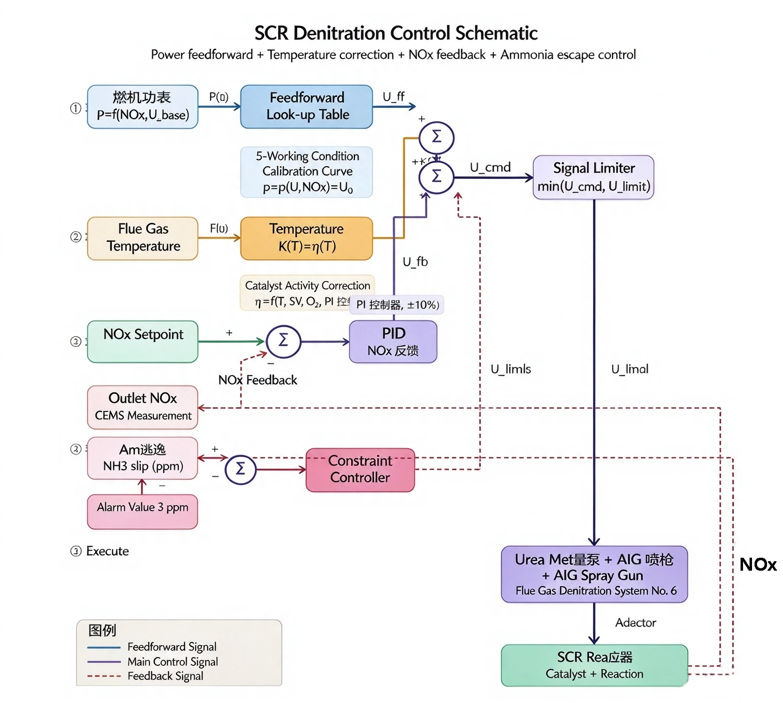
Figure 3 Composite Control Block Diagram of SCR Denitrification
6.4 Description of Control Loops
Final control output: \(U_{\text{final}} = \min(U_{\text{ff}} \times K(T) + U_{\text{fb}}, U_{\text{limit}})\). Feedforward ensures fast response, feedback ensures accuracy, and ammonia slip constraint ensures operational safety.
| Loop | Function | Purpose |
|---|---|---|
| ① Power Feedforward | Gas turbine power P(t) → feedforward look-up table → baseline urea flow U_ff; delay < 1 s, anticipates load changes | Fast response |
| ② Temperature Model Correction | Flue gas temperature T(t) → catalyst activity correction K(T) × η(T); η = f(T, SV, age) | Compensate for temperature drift |
| ③ NOx Feedback | NOx_sp − NOx_out → PID → U_fb; fine-tuning range ±10% | Eliminate deviation |
| ④ NH₃ Slip Constraint | NH₃_slip compared against 3 ppm limit → constraint controller; output U_limit | Safety protection |
6.5 Signal Interface Requirements
| Signal | Source | Type | Purpose |
|---|---|---|---|
| Gas Turbine Power | Gas Turbine DCS | 4–20 mA / Modbus / OPC UA | Main feedforward signal |
| Ambient Temperature | Gas Turbine DCS or on-site PT100 | 4–20 mA / RTD | Second feedforward variable |
| Inlet NOₓ/O₂ | CEMS | 4–20 mA / Digital | Emission monitoring |
| Outlet NOₓ/O₂ | CEMS | 4–20 mA / Digital | Feedback control |
| Outlet NH₃ | NH₃ analyzer or FTIR | 4–20 mA / Digital | Ammonia slip constraint |
7. Conclusions and Recommendations
- This project uses 32.5% aqueous urea solution (AdBlue) instead of ammonia gas as the SCR reducing agent, which outperforms the original scheme in safety, economy and operation & maintenance convenience.
- The flue gas temperature range of 510–529 ℃ fully meets the requirements for SCR reaction and urea pyrolysis; the overall temperature drop is less than 2 ℃, and the pressure drop is approximately 1.2–2.4 kPa. The system is technically feasible.
- For the large cross-section of DN2000, an AIG array with 6 injectors (1 central + 5 outer) must be adopted to meet the mixing uniformity requirement. Air-assisted nozzles are recommended, with SMD controlled at approximately 30 μm.
- The composite control strategy of power feedforward + temperature model correction + NOₓ feedback + ammonia slip constraint is recommended for the control system. The gas turbine feedforward lookup table shall consider both power and ambient temperature.
- It is recommended that after the manufacturer supplements complete design data in the next stage, detailed verification shall be performed with SCR calculation tools, and CFD atomization and mixing simulation shall be carried out for validation.
Post time: Oct-29-2026