
I. Operating Principle of the SCR System
Ammonia is injected into the high-temperature flue gas denitrification unit as the denitrifying agent. Under the action of the catalyst, NOₓ in the flue gas is reduced to N₂ and H₂O. The reaction equations are shown below:
\(\ce{4NO + 4NH3 + O2 -> 4N2 + 6H2O}\)
\(\ce{NO + NO2 + 2NH3 -> 2N2 + 3H2O}\)
With a suitable catalyst, the above reactions can proceed efficiently at a temperature range of 200 ℃ ~ 450 ℃. A denitrification efficiency of 80–90% can be achieved when the molar ratio of NH₃/NO equals 1.
The concentration of NOₓ in flue gas is generally low, while the flue gas volume is relatively large. For this reason, catalysts used in SCR systems must deliver high performance. Catalysts working under such conditions shall meet the requirements for highly reliable operation of coal-fired boilers.
II. Features of Flue Gas Denitrification Technology
Thanks to its high removal efficiency and compliance with current environmental regulations, SCR denitrification technology has attracted great attention and been widely adopted in the power sector. In developed countries with stringent environmental requirements, such as Germany, Japan, the United States, Canada, the Netherlands, Austria, Sweden and Denmark, SCR is among the most widely applied and mature denitrification technologies. Based on experience from developed economies, SCR denitrification technology will inevitably become the primary denitrification solution for coal-fired boilers in thermal power plants in China and gain broader application.
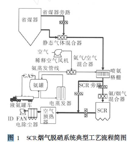
Figure 1 shows the schematic diagram of the typical process flow of the SCR flue gas denitrification system.
III. General Components of the SCR Denitrification System
Figure 1 shows the schematic diagram of the typical process flow of the SCR flue gas denitrification system. The SCR system generally consists of an ammonia storage system, ammonia-air mixing system, ammonia injection system, reactor system, economizer bypass, SCR bypass, detection and control system, etc.
Liquid ammonia is delivered from the liquid ammonia tank truck to the liquid ammonia storage tank by an unloading compressor. It is then evaporated into ammonia gas in the evaporator tank. The ammonia gas flows through the ammonia buffer tank and conveying pipeline into the boiler area. After being uniformly mixed with air, it is fed into the SCR reactor for reaction via distribution guide valves. The SCR reactor is installed upstream of the air preheater. Above the SCR reactor, ammonia gas is evenly distributed and mixed with flue gas through a special spraying device. The mixed flue gas passes through the catalyst layers inside the reactor to undergo the reduction reaction.
Key Technical Design Parameters of the SCR System
The main technical design parameters of the SCR system include the NOₓ concentration at the reactor inlet, reaction temperature, space velocity inside the reactor or residence time of the reducing agent, NH₃/NOₓ molar ratio, ammonia slip, and denitrification efficiency of the SCR system, etc.
1. Ammonia Storage and Mixing System
The ammonia storage system for each SCR reactor consists of one ammonia storage tank, one ammonia/air mixer, two air compressors for ammonia dilution (one standby), valves, and an ammonia evaporator. The ammonia storage tank can hold anhydrous ammonia for 15 days of operation, filled up to 85% of the tank volume, and is equipped with a liquid level gauge and temperature indicator. Liquid ammonia is vaporized by electric heating, and the pressure inside the ammonia/air mixer is maintained at 350 kPa. The uniformity and dispersion of the mixture of NH₃ and flue gas are critical to maintaining low ammonia slip. To achieve good dispersion and uniform mixing of flue gas and ammonia in the flue duct, the following measures can be adopted: install a static mixer upstream of the reactor; increase the injection energy of NH₃; increase the number and coverage of injection points; improve the dispersion and direction of injection; install guide baffles in the flue duct after ammonia injection. Meanwhile, the structure of the ammonia injection system shall be optimized based on cold flow model test results and numerical flow simulation results.
2. Ammonia Injection System
The ammonia injection system regulates the ammonia injection rate according to feedback signals measured from boiler load, NOₓ concentration at the reactor inlet, and NOₓ concentration at the reactor outlet.
3. Reactor System
The SCR reactor adopts a fixed-bed configuration with catalysts arranged in modules. The number of catalyst layers inside the reactor depends on the required catalytic reaction surface area. A typical arrangement includes 2 to 3 catalyst layers. Above the top catalyst layer lies a non-catalytic flow straightening layer, which ensures uniform distribution of flue gas entering the catalyst bed. Usually, a spare space is reserved below the third catalyst layer for adding a fourth catalyst layer when catalyst activity declines. Soot blowers are installed between catalyst layers inside the reactor for periodic soot blowing. The blowing duration ranges from 30 to 120 minutes, 1 to 2 times per week. Periodic internal cleaning of the reactor shall be performed if necessary. A hopper is arranged at the bottom of the reactor, connected to the power plant ash removal system for regular ash discharge.
4. Economizer and Reactor Bypass System
A bypass installed upstream of the economizer and between the reactor is called the economizer bypass. When the boiler load drops, flue gas flow decreases and the flue gas temperature entering the reactor falls below the required value, the bypass opens to introduce high-temperature flue gas into the reactor and raise the internal temperature. In addition, a large bypass is fitted between the inlet and outlet of the reactor, known as the reactor bypass. It is used under low boiler load conditions, such as unit start-up and shutdown, low-load operation and seasonal operation, to prevent catalyst poisoning and contamination caused by low temperature. All slide gate valves for SCR system bypasses shall guarantee zero leakage.
5. Catalyst
The catalyst is the core of the SCR process for power plants, accounting for approximately one-third of the total investment. For safe and economical operation of the power station, the catalysts used in the SCR process shall meet the following requirements:
- High activity over a wide low-temperature range
- High selectivity (low conversion rate of SO₂ to SO₃ and minimal side reactions)
- Chemical stability against sulfur dioxide (SO₂), halogen acids (HCl, HF), alkali metals (Na₂O, K₂O) and heavy metals (e.g., As)
- Stability against severe temperature fluctuations
- Low flue gas pressure drop
- Long service life and low cost
An ideal catalyst shall have the following advantages:
- High activity
- Strong anti-poisoning capability
- Good mechanical strength and abrasion resistance
- Suitable operating temperature window
① Basic Concept of SCR Catalysts
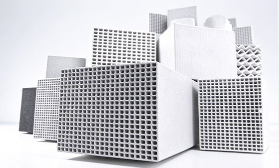
Catalyst Types Shape: The initially developed catalysts were granular. Nowadays, honeycomb or plate-type catalysts are adopted to avoid catalyst bed clogging by dust and reduce pressure drop. The cell pitch of such catalysts can be selected according to the dust concentration in exhaust gas. Figure 2 shows the appearance of honeycomb catalysts.
Composition: In general, a catalyst consists of:
① Substrate (the skeleton forming the catalyst)
② Support (a material that enables good dispersion and retention of active metal components)
③ Active metal (the component responsible for catalytic reaction)
However, the honeycomb catalysts currently in use do not adopt a separate substrate. Instead, the support material itself serves as the substrate and is formed into a honeycomb structure.
Table 1 shows the structure and functions of the catalyst.
| Component | Function | Composition |
|---|---|---|
| Substrate | Skeleton for maintaining catalyst shape | Steel, Ceramic |
| Support | Dispersion and retention of active metals | TiO₂ |
| Active Metal | Provide catalytic activity | V₂O₅, WO₃, MoO₃ |
② Catalyst Performance
The factors that have a significant impact on catalyst performance include reaction temperature, catalyst loading, and ammonia injection rate, as shown in Figure 3.
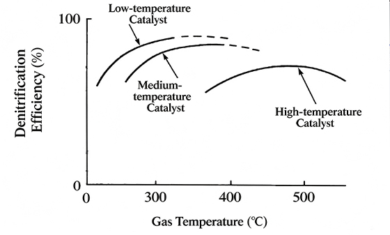
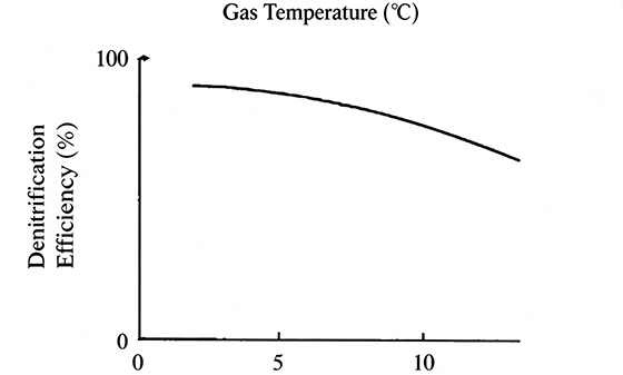
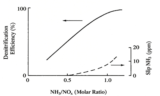
Since the catalyst exhibits optimal activity at 250~450 ℃ (preferably 350~400 ℃), the denitrification reaction is normally designed within this temperature window. If the reaction temperature falls outside this range, catalyst performance will degrade. Especially at high temperatures, overheating causes sintering of the catalyst surface, shortening its service life.
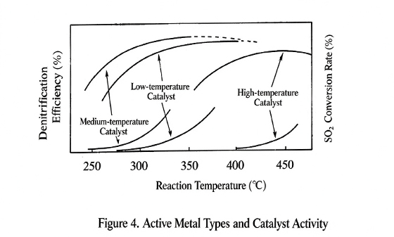
Nevertheless, with the expanding application scope of denitrification units in recent years, a broader operating temperature range for catalysts is also required. Examples include low-temperature catalysts for waste incinerators operating at 200 ℃ (denitrification units installed at the bag filter outlet), and high-temperature denitrification catalysts for single-cycle gas turbines with reaction temperatures above 550 ℃ (denitrification units fitted at the turbine outlet). The temperature dependence of the catalyst is determined by the concentrations and ratios of its active components (V₂O₅, WO₃, etc.). By properly selecting the composition of active metals, catalysts with optimal properties tailored for diverse applications can be manufactured. Figure 4 shows the relationship between active metal types and catalyst activity.
6. SCR Measurement and Control System
① Reaction Temperature Control
Within a certain temperature range, the NOₓ removal rate rises sharply as the reaction temperature increases. After the denitrification efficiency reaches its peak, further temperature rise will oxidize NH₃ and reduce the denitrification rate. If the reaction temperature is too low, the flue gas denitrification reaction cannot proceed sufficiently, and ammonia slip is likely to occur. Therefore, the flue gas temperature at the SCR inlet shall be monitored, and the temperature is regulated by adjusting the opening of the economizer bypass.
② Ammonia Flow Control
When the NH₃/NOₓ molar ratio is less than 1, denitrification efficiency improves significantly with an increase in the NH₃/NOₓ molar ratio. Excessive ammonia injection will cause secondary pollution. Normally, the NH₃/NOₓ molar ratio is controlled at around 1.0. The ammonia flow control valve modulates the ammonia supply flow. The control system calculates the required ammonia feed flow based on the NOₓ concentration at the reactor inlet, flue gas flow rate, target NOₓ emission concentration at the reactor outlet and allowable ammonia slip concentration. To protect personnel and equipment safety, the ammonia shut-off valve closes automatically under the following conditions: low flue gas flow; high ammonia-air ratio; excessively high flue gas temperature at catalyst inlet; excessively low flue gas temperature at catalyst inlet; no boiler run permission signal; emergency stop activation.
③ Ammonia Dilution Air Flow Control
The air flow for ammonia dilution is set during SCR commissioning and remains unchanged during operation. There are two air compressors, one for duty and one standby. When the discharge pressure of the primary air compressor drops below the setpoint or a fault occurs, the standby air compressor starts automatically. The ammonia evaporator is integrated with the storage tank. The heater is submerged in liquid anhydrous ammonia and controlled by the tank pressure. When the tank pressure falls below the set value, the heater is energized to vaporize liquid ammonia; power to the heater cuts off for overheat protection.
Post time: Oct-27-2026