
Abstract
Based on the R&D achievements of exhaust aftertreatment systems for gas internal combustion engines, this report takes the integrated system of DOC (Diesel Oxidation Catalyst) + SCR (Selective Catalytic Reduction) + ASC (Ammonia Slip Catalyst) as the framework. It first elaborates the technical challenges of the gas engine DOC in CO/HC oxidation (especially methane oxidation), as well as the system principle of the three-unit coordinated operation of DOC+SCR+ASC. On this basis, focusing on the SCR control system, it conducts an in-depth analysis of common problems prevailing in the SCR industry, including long pipeline errors, injector errors, flowmeter errors, catalyst efficiency issues and the limitations of traditional control systems. Meanwhile, it details the technical innovations and advantages of the new control system, including core software schemes such as feedforward control based on power emission factors, ammonia slip estimation via cross-sensitivity of NOₓ sensors, temperature-efficiency models, and load dump protection. It also discusses the coordination mechanism between ASC hardware backup and software algorithms. Through software algorithm optimization, intelligent control strategies and system-level hardware coordination, the new system effectively addresses many pain points of traditional aftertreatment systems, improves denitrification efficiency, reduces ammonia slip, and achieves more accurate and reliable emission control.
1 Overview of the SCR System
The SCR (Selective Catalytic Reduction) denitrification system is an environmental technology used to reduce nitrogen oxide (NOₓ) emissions in exhaust gas. Its core principle is to inject reducing agents such as ammonia or urea into exhaust gas under the action of a specific catalyst, so as to selectively reduce NOₓ into harmless nitrogen (N₂) and water (H₂O).
SCR systems are widely applied in the following fields: • Mobile sources: exhaust treatment for diesel vehicles, ships, non-road mobile machinery, etc. • Stationary sources: flue gas treatment for coal-fired power plants, cement kilns, steel plants, waste incineration plants, etc.
The core components of an SCR system include catalysts, reductant storage and injection devices, and a control system. Among them, the performance of the control system directly determines the denitrification efficiency, ammonia slip level and operational stability of the entire SCR system.
1.1 Full View of Gas Engine Exhaust Aftertreatment System — DOC+SCR+ASC Integrated Scheme
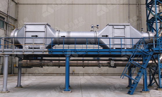
In practical engineering applications of gas internal combustion engines (especially lean-burn natural gas engines), the SCR system does not operate independently. Instead, it serves as a critical link in the exhaust aftertreatment chain, working in coordination with DOC (Diesel Oxidation Catalyst) and ASC (Ammonia Slip Catalyst) to form a complete emission control system.
System flow: Engine exhaust → DOC (Diesel Oxidation Catalyst) → Urea injection → SCR (Selective Catalytic Reduction) → ASC (Ammonia Slip Catalyst) → Stack emission
Three major functions of DOC: ① CO/HC oxidation: Oxidize carbon monoxide (CO) in exhaust gas into CO₂, and hydrocarbons (HC) into H₂O and CO₂. The light-off temperature of CO is approximately 150°C, and non-methane hydrocarbons (NMHC) light off at around 200°C. However, for natural gas engines, methane (CH₄), which accounts for the largest proportion in exhaust gas, has a C-H bond energy as high as 435 kJ/mol and requires a temperature above 400°C for effective oxidation. This is the biggest technical challenge for DOC. ② NO→NO₂ modulation: DOC partially oxidizes approximately 90% of NO in exhaust gas into NO₂, bringing the NO₂/NOₓ ratio close to 0.5. This is a prerequisite for the fast SCR reaction — the reaction rate of 2NH₃ + NO + NO₂ → 2N₂ + 3H₂O is an order of magnitude faster than that of standard SCR, and the efficiency improvement is especially remarkable in the low-temperature range (250~300°C). ③ Exhaust gas temperature rise: The exothermic effect of oxidation reactions provides a more stable temperature window for the downstream SCR.
Backup function of ASC: To achieve a NOₓ conversion rate above 95% in SCR, urea must be injected in excess (NH₃/NOₓ > 1.0), which inevitably generates ammonia slip (usually 5~20 ppm). Located at the very end of the system, ASC adopts a dual-layer catalyst design: the upper Pt/Al₂O₃ layer efficiently oxidizes NH₃ into N₂, while the lower SCR catalyst captures possible NOₓ by-products. It controls ammonia slip below 5~10 ppm as a physical safeguard to prevent secondary pollution.
The exhaust temperature of gas internal combustion engines is usually 350~500°C, which falls exactly within the optimal temperature window of DOC, SCR and ASC, serving as a natural advantage for efficient system operation. Nevertheless, the configuration of aftertreatment schemes varies significantly across application scenarios: lean-burn gas generator sets must adopt the DOC+SCR+ASC route; stoichiometric combustion natural gas engines use TWC (Three-Way Catalyst) + ASC; for sulfur-containing fuel gas (such as biogas), desulfurization pretreatment shall be added at the front end to prevent catalyst sulfur poisoning.
2 Common Problems in the SCR Industry
2.1 Long Pipeline Error
In air-assisted urea injection systems, long pipelines are usually connected between the pump and the injector. Errors induced by long pipelines are one of the key problems to be solved by the new system.
Nature of the core issue: The injection quantity is metered based on the flowmeter at the pump end or valve opening time, while the actual urea quantity sprayed into the exhaust pipe depends on the flow at the nozzle end. The long pipeline between the pump and injector is filled with liquid, resulting in severe metering errors.
Analysis of error types: ① Injection start delay (under-injection): After the command is issued, compressed air must push the liquid already in the pipeline to the nozzle before spraying occurs. If the control logic uses pump-end metering as the benchmark, the pump has supplied sufficient urea, but the nozzle has not finished spraying. Consequently, the actual urea entering the catalyst is less than the target quantity, leading to temporarily low NOₓ conversion efficiency. ② Post-stop trailing over-injection (over-injection): When the injection command stops, a liquid column remains in the pipeline. Although the air circuit is shut off, the liquid continues to flow out slowly due to inertia and gravity, forming trailing flow. The actual sprayed volume exceeds the target value and causes high ammonia slip concentration. ③ Cumulative error of multiple injections: The residual volume in the pipeline after each injection varies (affected by air pressure, temperature and liquid viscosity). The residual volume is superimposed on the initial state of the next injection, and the error amount differs each cycle. Therefore, simple fixed compensation coefficients cannot achieve effective correction.
Error quantification: Assuming a pipeline length of 10 meters, the residual volume is close to 200 ml. Such a large error directly causes inaccurate urea injection control.
2.2 Injector Error
The injector is a key component for urea atomization in the SCR system. Its performance directly affects urea atomization quality, mixing uniformity and denitrification efficiency.
Main problems: ① Insufficient atomization fineness: The fineness of hydraulic atomization is determined by the Weber number, i.e., injection pressure and nozzle aperture. Insufficient injection pressure or mismatched nozzle aperture leads to oversized urea droplets that cannot be fully vaporized in the flue duct, resulting in locally excessive or insufficient ammonia concentration. ② Improper injector installation: Urea injectors are generally installed in three modes: axial flue gas direction, perpendicular direction and inclined angle. An inappropriate installation angle causes wall impingement (urea sprayed onto the pipe wall), inaccurate injection volume and inadequate mixing, and further deviations in denitrification efficiency. ③ Injector coking and clogging: Urea solution tends to crystallize and coke on the injector surface under high-temperature conditions, altering the spray pattern and atomization quality, which destabilizes injection quantity and degrades atomization performance.
2.3 Flowmeter Error
Differential pressure flowmeters (such as pitot tube type) widely used in current SCR systems have multiple error sources, which seriously impair the accuracy of exhaust flow measurement and further affect the calculation precision of urea injection quantity.
Core measurement formula for differential pressure flowmeters: \(Q = C × A × \sqrt{2ΔP / ρ}\) Where: C = discharge coefficient, A = throttling area, ΔP = differential pressure, ρ = fluid density. Almost every parameter is subject to interference in the SCR exhaust environment.
Main error sources: ① Fluctuation of density ρ: Exhaust temperature variation changes density (the density at 200°C is nearly twice that at 400°C); moisture evaporation after urea injection leads to sharp local humidity changes and density fluctuation. Without temperature and pressure compensation, density error can directly cause a flow error of 10~20%. ② Pressure tapping holes are prone to blockage by urea crystallization: this is the most severe problem. After 32.5% urea solution is injected into the exhaust pipe, most of it evaporates and decomposes. However, the temperature near the pipe wall is low, and urea droplets hitting the probe surface easily crystallize at the edge of tapping holes. Once crystallized, the effective area of tapping holes decreases, the differential pressure signal attenuates and the flow reading is lower than actual value. Moreover, crystallization progresses gradually without fault alarms, and the error deteriorates silently. ③ Difference in thermal inertia between two probes: The large and small tubes of the pitot tube differ in surface area and heat capacity. Under variable temperature conditions, the two tubes respond to temperature at different rates, generating extra temperature differential pressure in the connecting pipelines of the differential pressure transmitter. This error is superimposed with dynamic temperature deviation especially under transient working conditions. ④ Disturbance from air-assisted injection: Pitot tube probes are directly exposed to the exhaust flow. If compressed air and urea atomization plume of air-assisted injection sweep across the probe, the jet stream impacts the tapping holes, the local dynamic pressure rises sharply, ΔP jumps instantaneously and sharp peaks appear in flow readings.
2.4 Catalyst-Related Issues
The catalyst is the core component of the SCR system, whose performance directly affects NOₓ conversion efficiency and ammonia slip level. The industry is generally confronted with the following catalyst-related problems: ① Temperature window limitation: Cu-SCR catalysts have a relatively high active temperature window. The efficiency is insufficient at 200°C (only 86% for fresh catalysts and 75% after aging), which is unsuitable as the operating temperature. The optimal operating range is 300~500°C, and the efficiency drops significantly when the temperature is below 250°C or above 550°C. ② Catalyst aging: High-temperature hydrothermal aging causes loss of active sites on catalysts; low-temperature active sites suffer the heaviest loss during high-temperature aging. After aging, the NOₓ conversion rate of the catalyst may decline, while the generation of N₂O by-products increases by 2~5 times in the medium and high temperature range (reaching 70 ppm at 600°C). N₂O is a potent greenhouse gas (its GWP is 273 times that of CO₂). ③ Cold zone effect: In SCR system design, the mixed gas of atomized urea, compressed air and flue gas enters the catalyst and reduces catalyst temperature. The endothermic urea hydrolysis reaction (ΔH = +150 kJ/mol) and physical sensible heat absorption by cold urea droplets cause local temperature drop. The instantaneous local temperature drop in the core of the injection plume can reach 70~100°C, pulling the local catalyst temperature from 320°C down to 150~250°C, which falls exactly in the temperature range (180~250°C) where ammonium sulfate ((NH₄)₂SO₄) is most likely to form, resulting in catalyst clogging and deactivation.
2.5 Limitations of Traditional Control Systems
Traditional SCR control systems mainly rely on exhaust flow detection and open-loop control, with the following limitations: ① Limitations of flow feedforward: Traditional systems calculate the final SCR injection quantity through real-time exhaust flow measurement. However, under actual working conditions, the relationship between exhaust flow and load (or fuel injection quantity) is often not perfectly linear. In particular, before and after turbocharger intervention, the flow will produce a non-linear jump. In addition, if ambient temperature or altitude changes, the volumetric flow rate and flow velocity of exhaust gas will change drastically even at a fixed load point, increasing ammonia slip. ② Response lag: When the equipment is subjected to a rapid load increase, fuel supply rises instantly and NOₓ is generated explosively. Nevertheless, due to fluctuations and lags in flow detection, the system only injects urea mechanically according to the current calculated value, causing response lag and severe short-term NOₓ emission exceedance. ③ Lack of adaptability: Traditional systems cannot compensate for calibration deviations caused by changes in the engine operating environment (high altitude, intake air temperature variation, engine condition changes). When the catalyst treatment efficiency decreases, the system has no self-regulation function and will lead to over-injection and ammonia slip. ④ Limitations of the five-point parameter map: Many traditional systems adopt the five-point method (25%, 50%, 75%, 90%, 100% load points) for feedforward control. This scheme works under steady-state conditions but has inherent drawbacks in dynamics and precision: distorted linear interpolation, neglected environmental correction and blind zones in transient conditions.
2.6 CO/HC Oxidation Challenges for DOC in Gas Internal Combustion Engines
In the DOC+SCR+ASC integrated system, DOC performance directly affects the denitrification effect of downstream SCR. For gas internal combustion engines, DOC faces the following unique challenges in CO/HC oxidation:
Fundamental difficulties in methane oxidation: Methane (CH₄) is the main component of THC (Total Hydrocarbons) in the exhaust of natural gas engines, accounting for 80~90%. The methane molecule contains no C-C bond, with a C-H bond energy as high as 435 kJ/mol, making it the least active among all hydrocarbons. At typical exhaust temperatures (300~400°C), the conversion rate of non-methane hydrocarbons (NMHC) can reach 80~90%, while the methane conversion rate may only be 30~50%. This means that the emission data measured by THC will be seriously underestimated due to the high proportion of methane. With the growing global concern over methane as a greenhouse gas (GWP = 28 times that of CO₂), methane slip has become a core issue in emission control for gas engines.
Influence of catalyst formulation on CO/HC oxidation: CO oxidation capacity: Pt (Platinum) > Pd (Palladium). Pt has the highest CO oxidation activity and a low light-off temperature. HC (NMHC) oxidation: Both Pt and Pd perform well, with a light-off temperature of approximately 200~250°C. CH₄ (methane) oxidation: Pd >> Pt. Pd is the preferred catalyst for methane oxidation, yet it requires high loading (>60 g/ft³) and sufficiently high temperature (>400°C).
Practical engineering formulation: Pt/Pd bimetallic formulation with typical loading of 30~90 g/ft³, balancing efficient oxidation of CO/NMHC and moderate methane conversion. Increasing the Pd ratio enhances methane oxidation capacity but raises the cost significantly.
Typical CO and HC conversion efficiency data (lean-burn gas engine, commercial DOC): CO conversion: 70~90% (T > 200°C) THC conversion: 50~90% (depends on CH₄/NMHC ratio) NMHC conversion: 80~90% (T > 250°C) CH₄ conversion: 30~60% (T > 400°C, requires high Pd loading) Oxygenated organics such as formaldehyde: >90% (relatively easy to oxidize)
Key engineering factors affecting DOC efficiency: ① Temperature: the most critical factor. For every 50°C below the light-off temperature, the efficiency may drop by 30~50%. When gas engines are cold-started or operated under low load, the exhaust temperature is insufficient, so an electric heater or burner shall be installed upstream of DOC for temperature compensation. ② Space Velocity (SV): typical design range 20,000~60,000 h⁻¹. Excessively high space velocity results in insufficient residence time and reduced oxidation efficiency. The design shall balance catalyst volume and backpressure. ③ O₂ concentration: Lean-burn engines have sufficient O₂ in exhaust (6~12%), which is favorable for oxidation reactions; stoichiometric combustion engines lack O₂, restricting CO/HC oxidation. ④ Sulfur poisoning: When the fuel contains H₂S, SO₂ is oxidized into SO₃ inside DOC, forming sulfate that covers Pt/Pd active sites and causing irreversible catalyst deactivation. For sulfur-containing fuel gas such as biogas and landfill gas, front-end desulfurization pretreatment is mandatory. ⑤ Competitive adsorption of water vapor: 10~15% water vapor in exhaust gas competes with CO/HC for catalyst active sites and inhibits oxidation reactions to a certain extent, especially in the low-temperature range.
Synergistic efficiency relationship between DOC and SCR: NO₂ generated by DOC acts as the “catalyst” for fast SCR reactions. When DOC aging or sulfur poisoning reduces the NO→NO₂ conversion efficiency, the NOₓ conversion rate of SCR declines synchronously, especially in the low-temperature range of 200~300°C. Therefore, DOC health monitoring and regular regeneration/replacement are the foundation to maintain the overall performance of the DOC+SCR+ASC system.
Post time: Oct-27-2026