
5. Installation Methods: Axial, Vertical, Angled — The Trade-off Between Spray Morphology and Mixing Efficiency
|
Installation Method |
Residence Time |
Mixing Efficiency |
Wall |
Applicable Scenarios |
|
Axial (Co-flow) |
Longest |
Low |
Lowest |
Long straight pipe sections, large diameters, high temperature |
|
Vertical (Cross-flow) |
Moderate |
High |
Highest |
Short mixing tubes, requiring rapid mixing |
|
Angled (Oblique) |
Longer |
Higher |
Moderate |
Optimal compromise |
5.1 Wall Impingement Risk Analysis for Vertical Installation
We currently adopt vertical installation. High mixing efficiency but highest wall impingement risk.
Non-impingement condition:
Lpen ≤ Dpipe - 2δ.
MR = (ρl·vl²)/ (ρg·vg²), the larger the MR, the farther the penetration distance.
Wall Impingement Hazard Chain
Urea wall impingement → wet pipe wall surface → incomplete pyrolysis →
condensation products/polymers → crystallization buildup → pipe wall corrosion & flow field distortion & injection quantity metering inaccuracy.
5.2 Optimization Potential for Angled Installation
Angled installation is more suitable for this project: droplets have axial velocity component (longer residence) & radial velocity component (cross-shear) & controllable radial penetration component. Optimal angle: αopt = arcsin((Dpipe-2δ)/ Lpen).
6. Spray Angle and Spray Distance: Engineering Constraints of Morphological Parameters
6.1 Spray Angle (Atomization Cone Angle)
The cone angle of a pneumatically assisted gun is jointly determined by nozzle structure and air-to-liquid ratio: at low ALR, cone angle is 30°~50° (concentrated liquid column, long penetration); at high ALR, cone angle is 60°~90° (dispersed droplets, short penetration).
Cone Angle-Pipe Diameter Matching Rule
Dcone(L) = 2L·tan(θ/2) ≤ 0.8 · Dpipe
Reverse calculation: θmax = 2 · arctan(0.4 · Dpipe/L)
Longer spray distance → smaller allowable cone angle - angle and distance must be jointly verified.
6.2 Spray Distance (Penetration Distance)
Penetration distance depends on the gas-liquid momentum ratio MR: Lpen/Dpipe ≈ k · MR0.5. Injection↑ → MR↑ → penetration↑ → impingement↑; Gas flow↑ → MR↓ → penetration↓ → impingement↓, but ALR↑ → cone angle↑. Numerical verification and balancing are required.
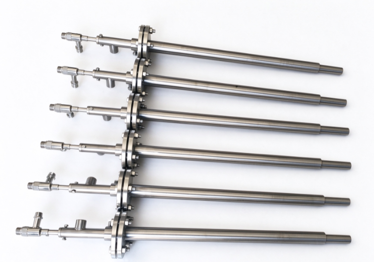
7. Liquid Line Pressure and Gas Line Pressure: Driving Parameters and Pipeline Coupling
7.1 Liquid Line Pressure
Effective pressure at nozzle end: ΔPl = Ppump - ΔPloss - Pback. Longer pipeline → greater pressure loss → lower nozzle-end pressure → decreased atomization quality & increased metering deviation. Shortening the pipeline is the fundamental measure to simultaneously solve atomization and metering problems.
7.2 Gas Line Pressure
Functions of gas line pressure: atomization drive, spray morphology control, pipeline purging, anti-crystallization. Typical settings: low load 0.2~0.3MPa (ALR 0.8~1.5, SMD 30~50μm); medium load 0.3~0.4MPa (ALR 0.3~0.8, SMD 50~80μm); high load 0.4~0.6MPa (ALR 0.15~0.3, SMD 80~120μm).
Problem of Excessively High ALR at Low Load
Automatically elevated ALR at low load → extremely fine atomization but excessive cone angle expansion → insufficient coverage cross-section.
Solutions:
l Appropriately reduce gas pressure
l Pulsed injection
l Soft sensing dynamic adjustment
8. Mixing Tube Design Coordination: Closed-Loop Matching of Gun and Pipeline
8.1 Reverse-Engineering Gun Parameters from Mixing Tube
(1) Calculate upper limit of evaporation time: tevap = Lmix / vg
(2) Reverse-calculate upper limit of SMD: determine D32,max by d² law
(3) Determine ALR range: ensure SMD ≤ D32,max
(4) Verify cone angle and penetration distance: no wall impingement & coverage ≥ 80% of pipe cross-section
(5) Determine nozzle orifice size and type
(6) Determine installation angle αopt
(7) Closed-loop verification: CFD simulation or bench testing
Core Contradiction of Mixing Tube-Gun Coordination
Short straight pipe section → requires small SMD → requires high ALR → large cone angle → high wall impingement risk → requires large pipe diameter → low flow velocity → long residence time → SMD requirement relaxed again. Do not pursue extreme SMD, taking a reasonable middle value of 50~80μm, leaving margin for cone angle and penetration.
9. Practical Gun Selection Procedure
Step 1: Determine SMD target = 60~80μm.
Step 2: Determine ALR range 0.3~1.0.
Step 3: Determine nozzle orifice (calculate at maximum conditions, verify ALR at low load).
Step 4: Verify whether cone angle and penetration distance satisfy non-impingement requirements.
Step 5: Determine installation angle (vertical if Lpen ≤ Dpipe/2 – δ, otherwise angled).
Step 6: Dynamic gas pressure adjustment strategy (proportional pressure reducing valve & PLC closed-loop).
Step 7: Pipeline optimization (shorten to ≤ 3m, inner diameter 4~5mm, gas line purging, insulation).
- Comprehensive Comparison and Recommendations for Gun Types
|
Spray Gun Type |
SMD Range |
|
ALR Requirement |
Penetration Distance |
Wall |
Pipeline Compatibility |
Rating |
||
|
Prefilming Air-Assist |
30-60μm |
60°-90° |
0.5-1.5 |
Short-Medium |
Excellent |
Excellent |
★★★★★ |
||
|
Coaxial Air-Assist |
50-100μm |
30°-60° |
0.3-0.8 |
Medium-Long |
Moderate |
Good |
★★★★ |
||
|
Multi-Orifice Air-Assist |
40-80μm |
Custom |
0.3-1.0 |
Short-Medium |
Excellent |
Moderate |
★★★★ |
||
|
Pure Hydraulic |
100-300μm |
Fixed |
None |
Long |
Poor |
Simple |
★★ |
Recommended Solutions
First Choice: Prefilming Air-Assist spray gun & angled installation - smallest SMD (30-60μm), controllable cone angle (60°-90°), moderate penetration, low wall impingement risk.
Alternative: Multi-orifice Air-Assist spray gun & vertical/small-angle installation - alternative solution when ALR is insufficient at high power.
Not Recommended: Pure hydraulic spray gun - particle size too large, non-adjustable, low-load contradiction cannot be resolved.
- Commissioning and Verification Methods
|
Parameter |
Monitoring Method |
Adjustment Method |
Adjustment Timing |
|
D32 |
Laser diffraction particle sizer / |
Indirect: ALR, gas pressure |
Selection & Initial commissioning |
|
Injection Quantity |
Pump-end flow meter & Collection method calibration |
Pump stroke/ Frequency |
Real-time |
|
Spray Angle |
High-speed camera / Laser sheet imaging |
Indirect gas pressure |
Initial commissioning |
|
Penetration Distance |
Visualization & Hot-wire anemometry |
MR adjustment |
Initial commissioning |
|
Liquid Line Pressure |
Nozzle-end pressure sensor |
Pump outlet & Pipeline optimization |
Real-time monitoring |
|
Gas Line Pressure |
Pressure reducing gauge |
Proportional pressure reducing valve |
Real-time closed-loop |
|
Gas Flow Rate |
Vortex / Thermal mass flow meter |
Pressure reducing valve & Pipeline |
Real-time monitoring |
|
Ammonia Slip |
Ammonia analyzer |
Injection quantity & Atomization combined |
Real-time closed-loop |
12. Summary
Key Points of Spray Gun Selection
(1) Target First: Reverse-calculate SMD from mixing tube constraints → reverse-calculate ALR → determine nozzle and gas pressure strategy.
(2) ALR is the Core Lever: Simultaneously controls SMD, cone angle and penetration distance; prioritize locking during commissioning.
(3) Installation Angle is the Key of Engineering: Vertical installation has high wall impingement risk; angled installation is the optimal compromise.
(4) Pipeline is the Hidden Enemy: Long pipelines simultaneously degrade
atomization and metering; shortening the pipeline is a systems-level solution.
(5) Dynamic Adjustment Is Indispensable: Gas line pressure should be dynamically adjusted based on load.
(6) Prefilming Air-Assist Spray Gun & Angled Installation is the optimal solution for the current project.
Part of the SCR Engineering System Series, alongside “SCR Flue Gas Flow Detection Issues and Solution Pathways”, “Long Pipeline Error Analysis”, and “Nozzle Installation Method Analysis”
Post time: Oct-16-2026