
Collaborative Analysis of Pneumatically Assisted Gun Parameters, Installation Methods, and Mixing Tube Design
Keywords: Pneumatically Assisted Spray Gun · Atomization Particle Size · Spray Angle · Spray Distance · Liquid/Gas Line Pressure · Mixing Tube Design · Wall Impingement Prevention
1. Problem Overview: The Spray Gun Selection Is More Than Just “Buying a Nozzle”
In SCR denitrification systems, urea injection is the sole bridge connecting metering and catalysis. The performance of the injection gun directly determines whether the urea solution can complete the entire process of atomization → evaporation → pyrolysis → mixing with NOx within the limited space and time. However, in actual engineering practice, the selection of spray gun often exists in a state of “passive adaptation” — procurement selection only checks whether the injection capacity meets requirements, installation location is chosen based on where drilling is convenient, and issues such as whether the atomization particle size matches the catalyst reaction rate, whether the spray angle matches the pipe diameter and straight pipe section length, and whether the spray distance causes wall impingement are often only discovered during the commissioning phase.
For systems using diaphragm metering pumps and pneumatically assisted spray guns, the problem of gun selection is even more complex. This is because the atomization quality of a pneumatically assisted spray gun simultaneously depends on the coordination of liquid phase parameters (flow rate, hydraulic pressure) and gas phase parameters (gas pressure, gas volume). Any deviation in a single parameter will propagate to the atomization particle size and spray morphology. Coupled with pipeline pressure loss, metering deviations between the nozzle end and pump end, and spatial constraints of the mixing tube, the selection of spray gun is a multi-parameter coupled systems engineering problem.
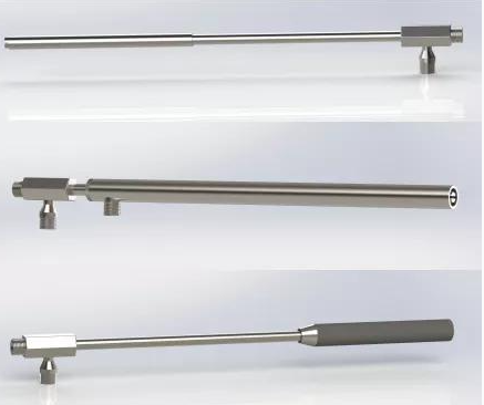
Core Argument
Gun selection is not an isolated selection task, but rather the solution of three coupled relationship groups: “atomization particle size ↔ catalyst reaction
kinetics”, “spray angle ↔ mixing tube geometry”, and “liquid/gas pressure ↔ pipeline pressure loss and metering accuracy”. The correct selection process is: first determine target particle size → reverse-calculate atomization conditions → select nozzle type → verify installation geometry → closed-loop verification
2. Atomization Mechanism: From Weber Number to Sauter Mean Diameter
2.1 Dual-Drive of Hydraulic and Pneumatic Atomization
The atomization of a pneumatically assisted gun is driven by two forces simultaneously:
Hydraulic atomization (hydraulic drive): The urea solution passes through the nozzle orifice under liquid line pressure and is ejected at a certain velocity. The relationship between jet velocity and pressure difference is v ∝ √ΔP, meaning that when pressure increases 4-fold, velocity only doubles.
Pneumatic atomization (aerodynamic shear): Compressed air undergoes high-speed collision with the liquid film/liquid column at the nozzle exit, further tearing liquid droplets through aerodynamic shear forces. The core advantage of pneumatically assisted spray guns is that pneumatic atomization is far less dependent on pressure than hydraulic atomization, achieving fine mist even at lower hydraulic pressures.
Weber Number (Atomization Fineness Criterion)
We = ρg · vrel² · d / σ
ρg = gas density; vrel = gas-liquid relative velocity; d = droplet/column diameter; σ = urea solution surface tension (~65 mN/m)
Key Deduction: We > 12 enters the secondary atomization zone; We > 40 enters the fine atomization zone. Pneumatically assisted spray guns improve the Weber number by increasing vrel, which is the fundamental reason for their superiority over pure hydraulic atomization.
2.2 Sauter Mean Diameter (SMD/D32) - The Gold Standard for Measuring Atomization Quality
The Sauter mean diameter D32 is defined as: total liquid droplet volume / total liquid droplet surface area, i.e., the equivalent spherical diameter that has the same volume-to-surface-area ratio as the actual droplet population. It is used rather than simple average diameter because SCR reaction rates depend on droplet surface area (evaporation rate ∝ surface area), while injection quantity depends on volume; SMD is precisely the ratio of these two quantities.
Empirical SMD Formula for Pneumatically Assisted Guns (Kim-Marshall Correction)
D32 = C · (ρl0.5 · σ0.5 · dnozzle0.5) / (ρg · vrel) · (ALR)-α
C = nozzle structure constant; ρl = urea solution density (~1090 kg/m³); σ = surface tension; dnozzle = orifice diameter; ALR = air-to-liquid ratio (Gas-to-Liquid Ratio); α = power exponent (0.5~0.8)
Core Relationships:
(1) Larger ALR → smaller SMD
(2) Higher gas-liquid relative velocity → smaller SMD
(3) Larger nozzle orifice → larger SMD
Basis for Determining Target Particle Size
The requirements of SCR catalysts for atomization particle size depend on the relationship between evaporation time and mixing tube length:
l D32 ≤ 50 μm: evaporation time < 0.1s, suitable for short mixing tubes (< 1m) or low exhaust temperature scenarios
l D32 ≤ 100 μm: evaporation time ~0.3s, suitable for medium mixing tubes (1~3m)
l D32 ≤ 200 μm: evaporation time ~1s, requires longer mixing tubes (> 3m), with risk of crystallization
l D32 > 200 μm: unsuitable for SCR injection
Our target: Combine with mixing tube design to control D32 in the range of 50~80 μm.
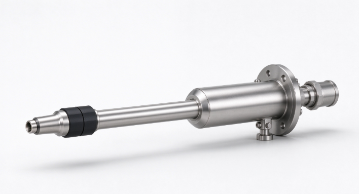
3. Gun Parameter System: Seven-Parameter Coupling and Priority Ranking
The operation of pneumatically assisted spray gun involves multiple parameters with strong coupling relationships among them. Clarifying the causal relationships and priorities of these parameters is the prerequisite for selection and commissioning.
|
Parameter |
Nature |
Control Authority |
Effect on SMD |
Effect on Spray Morphology |
Priority |
|
Breakup Size (D32) |
Target Parameter |
Selection & Commissioning |
— |
Indirectly affects evaporation and mixing |
★★★★★ |
|
Parameter |
Nature |
Control Authority |
Effect on SMD |
Effect on Spray Morphology |
Priority |
|
Air-to- (ALR) |
Core Driver |
Gas line gas volume |
ALR↑ → D32↓ |
Affects cone angle and penetration distance |
★★★★★ |
|
Liquid Line Pressure |
Driving Parameter |
Metering pump & pipeline loss |
ΔPl↑ → D32↓ (weak) |
Determines injection quantity and initial liquid column velocity |
★★★★ |
|
Gas Line Pressure |
Driving Parameter |
Air compressor & pressure |
ΔPg↑ → D32↓ (strong) |
Determines |
★★★★ |
|
Injection Quantity |
Constraint Parameter |
Pump stroke & nozzle orifice |
Injection↑ → ALR↓ → D32↑ |
Urea coverage |
★★★ |
|
Spray Angle |
Morphological Parameter |
Nozzle interaction |
Indirect |
Determines coverage cross-section and wall impingement risk |
★★★ |
|
Spray Distance |
Morphological Parameter |
Gas-liquid momentum ratio |
Indirect |
Determines wall impingement and coverage depth |
★★★ |
Parameter Priority Conclusions
l First Priority: Air-to-Liquid Ratio ALR — the strongest control variable for SMD. For every 0.1 increase in ALR, SMD can decrease by 15%~25%. ALR should be locked first during commissioning.
l Second Priority: Liquid line pressure / Gas line pressure - the underlying drivers of ALR, requiring coordinated adjustment.
l Third Priority: Spray angle and spray distance - adaptation parameters under installation geometry constraints.
4. Nozzle Orifice Calculation: The Contradiction Between Injection Quantity and Atomization Particle Size
The nozzle orifice directly determines the maximum injection capacity and atomization particle size baseline: larger orifice → higher flow upper limit → but thicker liquid column → aerodynamic shear requires more energy.
There exists a fundamental contradiction: high power requires large injection quantity → requires large orifice → unfavorable for atomization refinement.
Pneumatically assisted guns can still achieve target SMD range through sufficient ALR, but excessively high ALR increases compressed air consumption and causes excessive cone angle expansion.
Nozzle Orifice Selection Formula
dnozzle = √(4Qtarget / (π · Cd · √(2ΔPl/ρl)))
Practical Recommendation: First calculate dnozzle based on maximum operating conditions, then verify whether ALR at minimum operating conditions ≥ 0.5. If insufficient, consider a multi-orifice solution.
4.1 Single Orifice vs. Multi-Orifice Nozzles
Single Orifice Nozzle:
l Simple structure, low cost
l Wide flow adjustment range
l Relatively large atomization particle size (concentrated liquid column);
l Cone angle determined by airflow structure, limited range
l Suitable for small injection quantities and small pipe diameters
Multi-Orifice Nozzle:
l Complex structure, large nozzle-end size
l Small single-orifice flow → total flow can be split
l Significantly reduced atomization particle size
l Cone angle can be designed as sector/annular coverage
l Suitable for large injection quantities and large pipe diameters
Hidden Risks of Multi-Orifice Nozzles
Jet interference exists between orifices - overlapping regions of adjacent spray cones cause droplet collision and coalescence, increasing local particle size. Orifice spacing should be ≥ 2 × spray distance × tan(half-cone angle)
Post time: Oct-15-2026