
4. Comparative Analysis of Main Differential Pressure Flow Measurement Methods
The following provides a detailed analysis of the performance of five mainstream differential pressure flowmeters in SCR application scenarios.
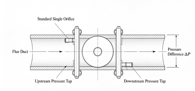
4.1 Standard Orifice Plate (Single Orifice)
The most classic throttling element, featuring a thin plate with a circular hole installed in the pipeline, measuring flow rate through the differential pressure before and after the orifice plate.
Advantages:
- Simplest structure, lowest cost, highest degree of standardization (ISO 5167)
- Mature theory and complete calculation models
- Wide range of applicable pipe diameters
Disadvantages (in SCR scenarios):
- High pressure loss: Pressure loss can reach 50%-70% of the differential pressure, adversely affecting engine back pressure
- Highest straight pipe section requirements: Requires 20D~40D upstream, which is almost impossible to meet at SCR sites
- Poor low-flow performance: When the Reynolds number falls below the limit value, the flow coefficient changes drastically, and the nonlinear error increases
- Prone to wear and ash accumulation: Flow coefficient drifts after the sharp edge of the orifice plate wears; particulate matter adhesion changes the flow area
- Small rangeability: Typically 3:1, barely reaching 4:1, unable to cover the full SCR operating range
Conclusion: Standard single orifice plates are not recommended for SCR flue gas flow measurement, unless the pipe diameter is very small and straight pipe section requirements can be met.
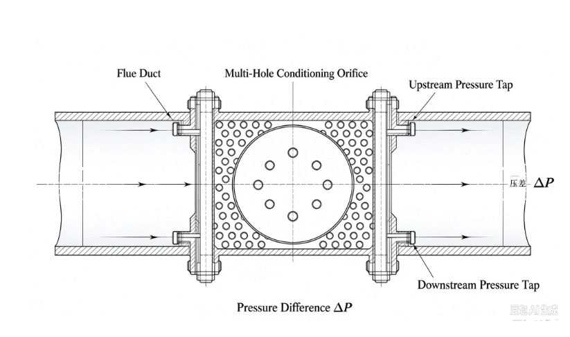
4.2 Multiplex Orifice Plate (Flow Conditioner Orifice Plate / Conditioning Orifice Plate)
Multiplex orifice plates (such as Rosemount 4050 and other multi-variable conditioning orifice plates) feature multiple circular holes on a single plate. The distribution of the holes is specially designed to possess both throttling and flow conditioning functions.
Advantages:
- Significant flow conditioning effect: The multiplex distribution makes the flow velocity profile more uniform, reducing the upstream straight pipe section to 2D~5D, making it highly suitable for space-constrained SCR scenarios
- Reduced pressure loss: Compared to single orifice plates, pressure loss is reduced by more than 50%
- Fouling resistance: The multiplex structure is less likely to be completely blocked compared to single holes, and the airflow between holes mutually scours, providing a certain degree of self-cleaning effect
- Acceptable accuracy: Accuracy can reach ±1%~1.5% after calibration
- Improved rangeability: Can reach 4:1~6:1
Disadvantages:
- Cost is 2~3 times higher than standard orifice plates
- The fundamental contradiction of weak differential pressure signals at low flow rates remains unresolved
- High machining accuracy requirements for multiplex holes; non-standard designs require CFD simulation verification
Evaluation: Multiplex orifice plates are a cost-effective compromise solution for SCR scenarios, with obvious advantages especially when straight pipe sections are limited. However, they must be used in conjunction with low-range differential pressure transmitters and temperature-pressure compensation.
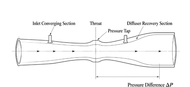
4.3 Venturi Tube
Composed of an inlet converging section, a throat, and an outlet diverging section. The streamlined structure allows the fluid to smoothly accelerate and then decelerate to recover pressure.
Advantages:
- Minimum pressure loss: Pressure recovery rate can reach 75%-90%, minimizing the impact on engine back pressure, which is an important advantage in SCR applications
- High accuracy: Accuracy can reach ±0.5%~1% after calibration
- Large rangeability: Can reach 6:1~10:1
- Wear resistance: Streamlined structure has no sharp edges, so wear has little impact on the flow coefficient
- Moderate straight pipe section requirements: 5D~10D upstream, much lower than orifice plates
Disadvantages:
- Large volume: The total length of a Venturi tube is typically 3D~8D, making installation difficult in compact SCR exhaust pipelines
- High cost: Complex machining, with costs significantly increasing for large pipe diameters
- Throat prone to ash accumulation: Flow velocity is highest at the throat, and high particulate content may accelerate wear
- Throat differential pressure remains very small at low flow rates, requiring high-sensitivity differential pressure transmitters
Evaluation: Venturi tubes are optimal in terms of pressure loss control and accuracy, suitable for applications sensitive to engine back pressure. However, volume and cost are their main limiting factors. For high-power engines or stationary source SCR (such as generator sets), if space permits, Venturi tubes are the preferred choice.
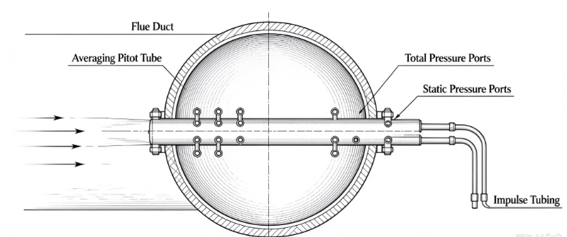
4.4 Annubar (Annubar / Averaging Pitot Tube)
Annubar (averaging pitot tube flowmeters) are based on the Pitot tube principle. A measuring rod is inserted along the diameter of the pipeline. Holes on the front face measure total pressure (multi-point average), and holes on the back face measure static pressure. The difference between the two is the average dynamic pressure.
Advantages:
- Extremely low pressure loss: The measuring rod has a small windward area, with pressure loss less than 1/10 of an orifice plate, barely affecting engine back pressure
- Convenient installation: Can be installed online (some models support hot-swapping); both flange and threaded installations are supported
- Moderate cost: Costs are much lower than Venturi tubes for large pipe diameters
- Multi-point pressure measurement: Multi-point pressure measurement on the measuring rod can approximate the average flow velocity of the pipe cross-section, providing some compensation for non-uniform flow velocity distribution
Disadvantages (in SCR scenarios):
- High straight pipe section requirements: Requires 15D~30D upstream, because the averaging pitot tube itself has no flow conditioning function and completely relies on the uniformity of the upstream flow field. This is a fatal shortcoming in SCR applications
- Weak signal: Measures dynamic pressure (an order of magnitude smaller than throttling differential pressure); differential pressure is extremely small at low flow rates, typically requiring capacitive high-sensitivity differential pressure transmitters
- Prone to blockage: Pressure measurement holes are small (1~3mm), and diesel carbon soot particles easily block them, requiring regular purging
- Poor pulsation resistance: Sensitive to exhaust pulsation, requiring damping treatment
- Rangeability is typically 5:1~8:1
Conclusion: Annubar performs excellently in industrial pipelines with large diameters, clean gases, and sufficient straight pipe sections. However, SCR exhaust scenarios are exactly the opposite—small diameters, particulate matter content, and insufficient straight pipe sections. Unless equipped with a pre-flow conditioner/straightener and blockage issues are resolved, its use in engine SCR is not recommended.
4.5 V-Cone Flowmeter (V-Cone)
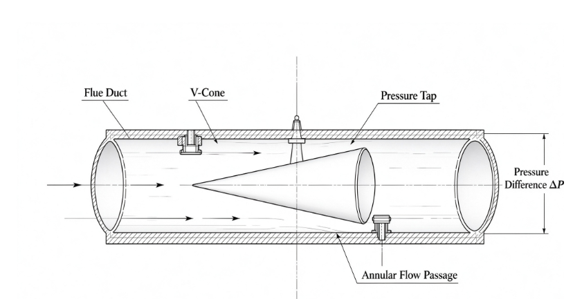
A cone is suspended in the center of the pipeline. Fluid bypasses the cone to form an annular channel where it accelerates, generating a differential pressure before and after the cone. The cone itself possesses both throttling and flow conditioning functions.
Advantages:
- Strongest flow conditioning effect: The cone has a “reshaping” effect on the flow field, requiring only 0D~3D upstream and 1D~2D downstream. It is currently the differential pressure flowmeter with the lowest straight pipe section requirements
- High accuracy: Accuracy can reach ±0.5% after calibration, with repeatability of ±0.1%
- Large rangeability: Can reach 10:1~15:1, covering the wide operating range of SCR
- Moderate pressure loss: Pressure loss is 20%-40% of the differential pressure, better than orifice plates but inferior to Venturi tubes
- Fouling resistance: The cone surface is streamlined, making it difficult for particulate matter to adhere; the annular flow channel has a self-scouring effect
- Signal enhancement: Compared to orifice plates, differential pressure is larger under the same flow rate, which is beneficial for low-flow measurement
Disadvantages:
- Higher cost: High machining accuracy requirements for the cone, with prices 3~5 times that of standard orifice plates
- Non-standard design: Requires customization based on specific pipe diameters and operating conditions, unlike orifice plates which have universal standard parts
- The cantilever structure of the cone carries fatigue risks in strong pulsating exhaust; the vibration environment must be evaluated
Evaluation: V-Cone flowmeters perform the most comprehensively in SCR scenarios with limited straight pipe sections and wide operating ranges. Its “built-in flow conditioning” characteristic almost perfectly solves the core pain point of insufficient straight pipe sections at SCR sites. Although the cost is high, considering the saved straight pipe section space and comprehensive performance, it is one of the optimal choices for SCR flue gas flow measurement.
4.6 Comprehensive Comparison
|
Comparison Item |
Standard Orifice Plate (Single) |
Multiplex Orifice Plate |
Venturi Tube |
Annubar (Averaging Pitot Tube) |
V-Cone |
|
Accuracy |
±1%~2% |
±1%~1.5% |
±0.5%~1% |
±1%~2% |
±0.5% |
|
Rangeability |
3:1~4:1 |
4:1~6:1 |
6:1~10:1 |
5:1~8:1 |
10:1~15:1 |
|
Pressure Loss |
High (50-70% ΔP) |
Medium (30-50% ΔP) |
Low (10-25% ΔP) |
Extremely Low |
Medium (20-40% ΔP) |
|
Upstream Straight Pipe Section |
20D~40D |
2D~5D |
5D~10D |
15D~30D |
0D~3D |
|
Fouling Resistance |
Poor |
Relatively Good |
Medium |
Poor (Prone to Blockage) |
Good |
|
Low-Velocity Performance |
Poor |
Medium |
Medium |
Poor |
Relatively Good |
|
Cost |
Lowest |
Medium |
High |
Medium |
Relatively High |
|
SCR Applicability |
Not Recommended |
Usable |
Recommended |
Not Recommended |
Most Recommended |
5. Hybrid Straight Pipe Section Optimization and Flow Field Conditioning
5.1 Mechanism of Insufficient Straight Pipe Section Effects
The flow coefficient C of a differential pressure flow meter is calibrated under fully developed pipe flow conditions. When upstream flow obstructions such as elbows, reducers, or valves are present, the velocity profile deviates from the typical 1/7th power law distribution, resulting in the following distortions:
l Asymmetric Velocity Profile: The velocity is high on one side and low on the other downstream of an elbow, causing the cross-sectional average dynamic pressure to deviate from the calibrated value.
l Secondary Flow/Vortex: Elbows generate vortices, causing the fluid to advance in a helical pattern and resulting in periodic fluctuations in differential pressure readings.
l Enhanced Pulsation: Upstream flow obstructions exacerbate flow field pulsation, increasing noise in the differential pressure signal.
These distortions cause the flow coefficient to deviate from the calibrated value. The deviation varies non-linearly with flow rate, making it difficult to correct using a fixed coefficient.
5.2 Flow Conditioner Solutions
When physical straight pipe sections cannot meet requirements, flow conditioners (straighteners) should be installed to reduce the required straight pipe length. Common types of flow conditioners include:
|
Flow Conditioner Type |
Structure |
Flow Conditioning Effect |
Pressure Loss |
Required Upstream Straight Pipe Section (Reduced To) |
|
Tube Bundle Flow Conditioner (19-tube bundle) |
Parallel tube bundle |
Good |
Low |
Approx. 10D |
|
Zanker Plate Flow Conditioner |
Multiplex orifice plate + Grid |
Very Good |
Medium |
Approx. 5D~8D |
|
Multiplex Orifice Plate Flow Conditioner (Etoile/Star) |
Star-shaped multiplex orifice plate |
Good |
Low~Medium |
Approx. 5D~10D |
|
Nova Ultra-Compact Flow Conditioner |
Special 3D structure |
Excellent |
Medium |
Approx. 2D~3D |
Engineering Recommendation: For compact SCR piping, a combination of a multiplex orifice plate flow conditioner and a V-Cone or multiplex orifice plate is recommended. Installing the flow conditioner 2D~3D upstream of the flow meter can correct the velocity profile to an acceptable range. This dual-conditioning approach (“flow conditioner + self-conditioning throttling element”) can maintain the flow coefficient deviation within ±2% even under severe conditions with only 3D~5D downstream of an elbow.
Post time: Oct-13-2026