
5. Hybrid Straight Pipe Section Optimization and Flow Field Conditioning
5.1 Mechanism of Insufficient Straight Pipe Section Effects
The flow coefficient C of a differential pressure flow meter is calibrated under fully developed pipe flow conditions. When upstream flow obstructions such as elbows, reducers, or valves are present, the velocity profile deviates from the typical 1/7th power law distribution, resulting in the following distortions:
l Asymmetric Velocity Profile: The velocity is high on one side and low on the other downstream of an elbow, causing the cross-sectional average dynamic pressure to deviate from the calibrated value.
l Secondary Flow/Vortex: Elbows generate vortices, causing the fluid to advance in a helical pattern and resulting in periodic fluctuations in differential pressure readings.
l Enhanced Pulsation: Upstream flow obstructions exacerbate flow field pulsation, increasing noise in the differential pressure signal.
These distortions cause the flow coefficient to deviate from the calibrated value. The deviation varies non-linearly with flow rate, making it difficult to correct using a fixed coefficient.
5.2 Flow Conditioner Solutions
When physical straight pipe sections cannot meet requirements, flow conditioners (straighteners) should be installed to reduce the required straight pipe length. Common types of flow conditioners include:
|
Flow Conditioner Type |
Structure |
Flow Conditioning Effect |
Pressure Loss |
Required Upstream Straight Pipe Section (Reduced To) |
|
Tube Bundle Flow Conditioner (19-tube bundle) |
Parallel tube bundle |
Good |
Low |
Approx. 10D |
|
Zanker Plate Flow Conditioner |
Multiplex orifice plate + Grid |
Very Good |
Medium |
Approx. 5D~8D |
|
Multiplex Orifice Plate Flow Conditioner (Etoile/Star) |
Star-shaped multiplex orifice plate |
Good |
Low~Medium |
Approx. 5D~10D |
|
Nova Ultra-Compact Flow Conditioner |
Special 3D structure |
Excellent |
Medium |
Approx. 2D~3D |
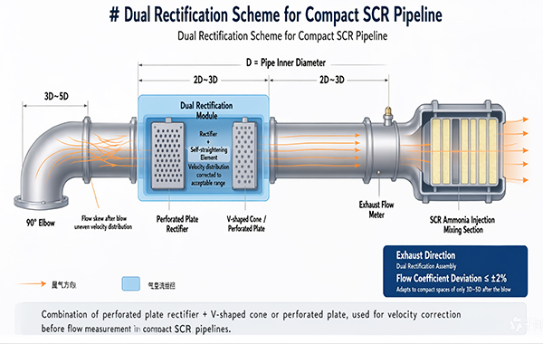
Engineering Recommendation: For compact SCR piping, a combination of a multiplex orifice plate flow conditioner and a V-Cone or multiplex orifice plate is recommended. Installing the flow conditioner 2D~3D upstream of the flow meter can correct the velocity profile to an acceptable range. This dual-conditioning approach (“flow conditioner + self-conditioning throttling element”) can maintain the flow coefficient deviation within ±2% even under severe conditions with only 3D~5D downstream of an elbow.
5.3 Integrated Design of Mixer and Flow Detection
SCR systems typically install a static mixer (to promote uniform mixing of urea and flue gas), which inherently disturbs the flow field. An optimization approach is to integrate the mixer with flow conditioning functions:
l The velocity profile downstream of the mixer will redevelop. Properly designed guide vanes at the mixer outlet can achieve both mixing and flow conditioning simultaneously.
l Positioning the flow meter 3D~5D downstream of the mixer utilizes the improved flow conditioning effect to optimize incoming flow conditions.
l Note: Turbulence generated by the mixer requires a certain distance to decay; placing the meter too close will result in excessive signal noise.
5.4 CFD Simulation-Driven Customized Design
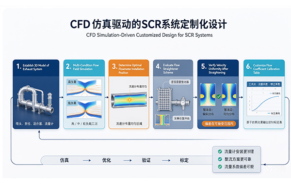
For SCR systems deployed in batches, it is highly recommended to use Computational Fluid Dynamics (CFD) simulation to optimize piping design:
(1) Establish a 3D model of the exhaust system (including elbows, reducers, mixer, and flow meter).
(2) Simulate flow field distribution at multiple operating condition points (high/medium/low load).
(3) Determine the optimal installation position for the flow meter (the point with the most uniform velocity profile).
(4) Evaluate the necessity of a flow conditioner and its installation position.
(5) Simulate and verify the uniformity of the velocity profile after conditioning to ensure deviations are within acceptable limits.
(6) Customize the flow coefficient calibration table based on simulation results.
6. Temperature and Pressure Compensation: The Overlooked “Second Source of Inaccuracy”
6.1 Necessity of Temperature and Pressure Compensation
The differential pressure measured by a differential pressure flow meter only reflects the operating condition volume flow rate, whereas SCR control requires the flue gas mass flow rate or standard condition volume flow rate. The conversion relationship is:
Qstandard = Qoperating × (Poperating / Toperating) × (Tstandard / Pstandard)
Among these, temperature has the most significant impact on density. Taking the SCR exhaust temperature range as an example:
|
Operating Condition |
Exhaust Temperature |
Flue Gas Density (Relative Value) |
Flow Error Without Compensation |
|
Low Load |
220°C (493K) |
1.00 (Baseline) |
— |
|
Medium Load |
350°C (623K) |
0.79 |
Approx. -12% |
|
High Load |
480°C (753K) |
0.65 |
Approx. -24% |
Without temperature and pressure compensation, when the temperature rises from 220°C to 480°C, the flow reading will be approximately 24% low. This means the ammonia injection rate will be about 24% low, directly leading to non-compliance with denitrification efficiency standards.
6.2 Compensation Implementation Plan
Complete temperature and pressure compensation requires the following sensors and calculations:
(1) Temperature Measurement: Install a K-type thermocouple or PT100 RTD 1D~2D downstream of the flow meter to measure flue gas temperature. Accuracy requirement: within ±2°C.
(2) Pressure Measurement: Install an absolute pressure transmitter near the flow meter to measure flue gas static pressure. Accuracy requirement: within ±0.5 kPa.
(3) Density Calculation: Calculate real-time flue gas density based on temperature, pressure, and flue gas composition (which can be set according to typical diesel/gas values or indirectly corrected by a NOx sensor).
(4) Flow Correction: Execute compensation calculations in real-time within the PLC/DCS to output the standard condition flow rate.
Key Conclusion: Temperature and pressure compensation is the optimization measure with the highest return on investment. The cost of adding one temperature sensor and one pressure transmitter is only a few hundred dollars, but it can eliminate 10%~40% of systematic errors. Discussing the accuracy of flow detection in SCR systems without temperature and pressure compensation is meaningless.
6.3 Impact of Flue Gas Composition on Density
Exhaust compositions vary significantly with different fuels, affecting density calculations:
|
Component |
Diesel Exhaust (Vol%) |
Gas Exhaust (Vol%) |
|
N₂ |
~75 |
~73 |
|
CO₂ |
~8 |
~10 |
|
H₂O |
~9 |
~17 |
|
O₂ |
~8 |
~0 |
|
Average Molecular Weight |
~28.5 |
~27.2 |
The density difference between diesel and gas exhaust is approximately 5%. For the same system with a fixed fuel type, calculations can be based on a fixed composition; if the fuel type is variable, dynamic correction based on O₂ sensor readings is required.
7. Flow Measurement Strategies Under Low-Load Conditions
The micro-differential pressure problem at low loads is the core challenge in SCR flow detection. The following strategies can be used in combination:
7.1 Dual-Range Differential Pressure Transmitter Scheme
Use two differential pressure transmitters with different ranges connected in parallel to measure the same differential pressure:
l High-Range Transmitter: Covers full-scale differential pressure (e.g., 0~2500 Pa) for medium to high loads.
l Low-Range Transmitter: Covers low-range differential pressure (e.g., 0~250 Pa) for low loads.
Smooth switching is performed in the overlapping zone to achieve a high rangeability (exceeding 30:1).
This scheme increases the cost by one transmitter but significantly improves measurement accuracy in the low flow region, making it the most direct and effective solution.
7.2 Variable Cross-Section / Adjustable Orifice Scheme
For V-Cone flow meters, the annular flow area can be changed by adjusting the cone position via a mechanism—reducing the flow area at low flows to increase differential pressure, and increasing the area at high flows to decrease differential pressure. This scheme can achieve constant differential pressure output with a rangeability exceeding 50:1, but the mechanism is complex and its reliability requires verification.
7.3 Soft Sensing Auxiliary Scheme
When physical measurement is unreliable in the low load region, soft sensing (virtual sensing) technology can be introduced:
l Estimate exhaust flow rate using engine speed, torque/power, intake air volume, exhaust temperature, and other parameters through empirical models or data-driven models.
l Use the differential pressure flow meter as the primary source in the medium to high load region, and switch to the soft sensing model in the low load region.
l Perform weighted fusion in the transition zone to ensure smooth switching.
Soft Sensing Model Reference: Exhaust Flow Rate ≈ Intake Air Volume × (1 + Fuel-Air Ratio) × (Texhaust / Tintake). The intake air volume can be estimated from intake pressure and engine speed, and the fuel-air ratio can be derived from an air-fuel ratio sensor or fuel injection volume. This method does not rely on differential pressure measurement and offers good stability in the low load region.
7.4 Feedback Correction Based on NOx Sensors
Even if feedforward flow measurement is inaccurate, SCR feedback control can still be corrected using the NOx concentration difference between the inlet and outlet. However, note the following:
l Feedback correction has a response lag (depending on catalyst volume and flow velocity) and cannot completely replace feedforward control.
l When feedforward error is too large, the feedback correction amount may exceed a reasonable range, causing ammonia injection oscillation.
l It is recommended to use feedforward as the primary control and feedback as secondary, keeping feedforward flow error within ±5%, with feedback only for fine-tuning.
8. Installation Location and System Layout Optimization
8.1 Principles for Flow Meter Installation Position
Core Principle: The flow meter must be installed upstream of the urea nozzle. This is a non-negotiable principle. SCR feedforward control requires the raw flue gas flow rate; any flow meter installed downstream of the ammonia injection point contains a fundamental conceptual error.
Reasons for installing the flow meter upstream of the nozzle include:
l The flue gas flow rate is not disturbed by the urea spray, reflecting the true exhaust state.
l The temperature field is uniform, making temperature and pressure compensation more accurate.
l There is no risk of urea crystallization/deposition, ensuring long-term stability of the throttling element.
l Clear control logic: Flow Signal → Calculate Ammonia Injection Rate → Execute Injection, forming a complete causal chain.
8.2 Alternatives for Insufficient Differential Pressure at Low Loads
If the flow meter must be installed upstream of the nozzle, resulting in insufficient differential pressure at low loads, the correct approach is:
(1) Select signal-enhancing throttling elements (V-Cone differential pressure is approximately 30%-50% higher than that of an orifice plate).
(2) Pair with a low-range, high-precision differential pressure transmitter (e.g., capacitive type, accuracy class 0.075).
(3) Adopt a dual-range transmitter scheme to expand rangeability.
(4) Introduce soft sensing assistance in the low load region.
Moving the flow meter downstream of the nozzle is not the solution; this merely solves an old problem by creating a new one.
8.3 Exhaust Piping Layout Optimization Recommendations
(1) Reserve Straight Pipe Sections During System Design: Between the engine turbocharger outlet and the SCR inlet, design a straight pipe section with a length no less than 5D.
(2) Use Large Radius Elbows: Use elbows with R ≥ 1.5D to reduce secondary flow intensity.
(3) Use Gradual Reducers: At diameter changes, use gradual reducers with a cone angle not exceeding 15° to avoid sudden contraction/expansion.
(4) Avoid Valves Upstream: Avoid installing valves upstream of the flow meter; if unavoidable, install a flow conditioner.
(5) Pressure Impulse Lines Design: Orient pressure taps downward or horizontally to prevent condensate accumulation; maintain a continuous downward slope for impulse lines; install condensate pots or isolation diaphragms.
9. Conclusions and Engineering Recommendations
9.1 Problem Summary
The issue of “inaccurate measurement and inaccurate calculation” in SCR flue gas flow detection is a systemic problem caused by the superposition of multiple factors:
Inaccurate Measurement: Weak differential pressure signal at low loads + flow field distortion due to insufficient straight pipe sections + particulate matter blockage/wear.
Inaccurate Calculation: Lack of temperature and pressure compensation + errors in operating/standard condition conversion + oversimplified density calculations.
Incorrect Installation: Flow meters installed downstream of the urea nozzle, which is a fundamental conceptual error.
9.2 Selection Recommendations
|
Application Scenario |
Recommended Solution |
Reason |
|
Compact space, straight pipe section < 3D (Mobile/On-vehicle SCR) |
V-Cone Flow Meter & Upstream Flow Conditioner |
Self-conditioning, lowest straight pipe requirement, maximum rangeability |
|
Medium space, straight pipe section 3~5D (Small/Medium Fixed Source) |
Multiplex Orifice Plate & Flow Conditioner |
Good cost-performance ratio, obvious flow conditioning effect |
|
Ample space, straight pipe section > 5D (High-power Generator Sets) |
Venturi Tube |
Highest accuracy, lowest pressure loss, suitable for large pipe diameters |
|
Large pipe diameter, clean exhaust (Gas Units) |
Annubar (Requires Flow Conditioner) |
Significant cost advantage for large pipe diameters |
|
Any Scenario |
Not Recommended: Standard Single Orifice Plate |
Excessive straight pipe requirement, high pressure loss, small rangeability |
9.3 Comprehensive Optimization Checklist
(1) Flow meters must be installed upstream of the urea nozzle - this is the baseline principle.
(2) Temperature and pressure compensation must be implemented - adding temperature and pressure sensors incurs very low costs but yields significant results.
(3) Select throttling elements with low straight pipe requirements - V-Cone or multiplex orifice plates are preferred.
(4) Install flow conditioners when straight pipe sections are insufficient - low investment with clear effects.
(5) Adopt dual-range transmitters or soft sensing assistance in the low load region - to solve micro-differential pressure measurement challenges.
(6) Implement anti-condensation design for pressure impulse lines - downward-facing taps, sloped piping, and regular purging.
(7) Use CFD simulation to optimize layout during system design - to determine optimal installation positions and conditioning schemes.
(8) Perform regular maintenance and calibration - inspect throttling elements for wear/ash accumulation and verify flow coefficients.
9.4 Outlook
As emission regulations become increasingly stringent and SCR control accuracy requirements rise, flow detection must transition from “having a measurement” to “measuring accurately.” Future trends worth noting include:
l The application of ultrasonic flow meters in flue gas measurement is gradually maturing, offering no pressure loss, high rangeability, and no moving parts, though current costs remain high.
l Thermal mass flow meters directly measure mass flow rate without requiring temperature and pressure compensation, but are significantly affected by particulate matter adhesion.
l Multi-sensor fusion: Multi-source fusion of differential pressure + thermal + NOx sensors + engine parameters to achieve high-precision flow estimation across all operating conditions.
l Digital Twin: Establishing digital models of SCR systems to fuse real-time measurement data with model predictions, achieving high-precision flow estimation through a combination of hardware and software.
However, before new technologies are applied on a large scale, getting existing differential pressure detection right — selecting the correct throttling element, installing it in the correct position, performing proper compensation, and optimizing the flow field — remains the most pragmatic and effective solution path currently available.
Disclaimer: This article is for technical discussion purposes. The data involved are for reference as typical values; specific engineering designs require calculation and verification based on actual operating conditions. The flow meter selection recommendations in this article are based on general engineering experience, and different application scenarios require comprehensive judgment based on actual conditions.
Post time: Oct-13-2026